Splitters of the CPL family are produced in FBT (Fused Bioconical Tapering) technology that is based on fusing narrowed cores of optical fibers. They are characterized by large resistance to varying conditions in external networks, low insertion and reflection losses. The FBT technology allows for adjustment of split ratio and operating range to the customer’s needs.

- Thermal stability of parameters
- Low insertion and polarization dependent losses
- Wide range of housings and fiber connectors
- Unlimited choice of power split ratio and unusual operating range
- Versions optimized for full 1260-1650 nm band available
- Possible custom solutions
- Test reports with full spectral profile of attenuation available on demand
- Passive optical networks: B-PON, G-PON, E-PON
- Telecommunication networks
- CATV networks
- Measuring equipment
Available splitter versions:
1x2 & 2x2:
- Single operation window, e.g. 1310 nm ± 40 nm
- Two operation windows, e.g. 1310/1550 nm ± 40 nm
- Three operation windows, e.g. 1310/1550 nm ± 40 nm & 1490 ± 10 nm
- Full 1260-1650 nm band
1x3 & 1x4:
- Single operation window, e.g. 1310 nm ± 40 nm
- Two operation windows, e.g. 1310/1550 nm ± 40 nm
- Three operation windows, e.g. 1310/1550 nm ± 40 nm & 1490 ± 10 nm
|
Example split ratios and corresponding attenuation for 1x2&2x2 splitters |
||||
|
Split |
Attenuation | |||
| One operation window | Two operation windows | Three operation windows | Full band | |
|
1/99 |
21.0 dB/0.2 dB |
23.5 dB/ 0.3 dB |
23.5 dB/0.30 dB |
24 dB/0.75 dB |
|
10/90 |
10.8 dB/0.6 dB |
11.3 dB/ 0.6 dB |
11.5 dB/0.75 dB |
11.8 dB/1.25 dB |
|
20/80 |
7.60 dB/1.2 dB |
7.85 dB/ 1.4 dB |
7.95 dB/1.50 dB |
8.8 dB/1.8 dB |
|
30/70 |
5.90 dB/1.9 dB |
6.00 dB/ 1.9 dB |
6.20 dB/2.10 dB |
6.7 dB/2.5 dB |
|
40/60 |
4.40 dB/2.5 dB | 4.70 dB/2.7 dB | 4.90 dB/2.90 dB | 5.3 dB/3.3 dB |
* Other ratio according to customer’s specification.
|
One operation window 1310 nm |
|||
| Type | 1x2/2x2 | 1x3 | 1x4 |
|
Power split |
1-50% |
33.3/33.3/33.3* |
25/25/25/25* |
|
Wavelengths |
1310 nm or 1550 nm or others |
||
|
Bandwidth |
± 40 nm |
||
|
Channel uniformity [dB] |
≤ 0.5 |
≤ 1.1 |
≤ 1.4 |
|
Max attenuation [dB] |
≤ 3.3@50/50 |
≤ 5.6 |
≤ 7.2 |
|
Max PDL [dB] |
≤ 0.15 |
||
|
Directivity [dB] |
≥ 55 |
||
|
Thermal stability |
0.002 dB/0C |
||
|
Temperature of operation |
-400C to +850C |
||
|
Two operation windows 1310&1550 nm |
|||
| Type | 1x2/2x2 | 1x3 | 1x4 |
|
Power split |
1-50% |
33.3/33.3/33.3* |
25/25/25/25* |
|
Wavelengths |
1310 & 1550 nm or others |
||
|
Bandwidth |
± 40 nm |
||
|
Channel uniformity [dB] |
≤ 0.6 |
≤ 1.1 |
≤ 1.4 |
|
Max attenuation [dB] |
≤ 3.6 @50/50 |
≤ 5.8 |
≤ 7.6 |
|
Max PDL [dB] |
≤ 0.15 |
||
|
Directivity [dB] |
≥ 55 |
||
|
Thermal stability |
0.002 dB/0C |
||
|
Temperature of operation |
-400C do +850C |
||
|
Three operation windows 1310&1490&1550 nm |
|||
| Type | 1x2/2x2 | 1x3 | 1x4 |
|
Power split |
1-50% |
33.3/33.3/33.3* |
25/25/25/25* |
|
Wavelengths |
1310&1490&1550 nm or others |
||
|
Bandwidth |
± 40 nm @1310&1550 nm |
||
|
Channel uniformity [dB] |
≤ 0.7 |
≤ 1.4 |
≤ 1.7 |
|
Max attenuation [dB] |
≤ 3.7 @50/50 |
≤ 6.0 |
≤ 7.8 |
|
Max PDL [dB] |
≤ 0.15 |
||
|
Directivity [dB] |
≥ 55 |
||
|
Thermal stability |
0.002 dB/0C |
||
|
Temperature of operation |
-400C do +850C |
||
|
Full band 1260-1650 nm |
|
| Type | 1x2/2x2 |
|
Power split |
1-50% |
|
Wavelengths |
1260-1650 nm |
|
Channel uniformity [dB] |
≤ 0.9 |
|
Max attenuation [dB] |
≤ 4.0 @50/50 |
|
Max PDL [dB] |
≤ 0.20 |
|
Directivity [dB] |
≥ 55 |
|
Thermal stability |
0.002 dB/0C |
|
Temperature of operation |
-400C do +850C |
* Other ratio according to customer’s specification.
Notice: Parameters listed in the table refer to components without connector terminations.
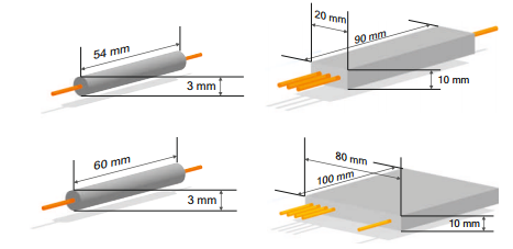
Cases:
- 1x2/2x2 splitters, 250/900 µm cable - 3x55 mm pipe
- 1x3/1x4 splitters, 250/900 µm cable - 3x60 mm pipe
- 1x2/2x2 splitters, 2.0/3.0 mm cable - 90x20x10 mm housing
- 1x3/1x4 splitters, 2.0/3.0 mm cable - 100x80x10 mm housing
- Products
- Optical Splitters and Couplers
- Cassette HD with PLC splitters
- Combiners
- FBT Optical Couplers
- Optical FPLC Splitters
- Asymmetrical 1x5 Splitters for FTTH Networks
- Optical Splitters in LGX Modules
- Optical Splitters in PZSP Patch Panels
- Multimode PLC Splitters
- WDM Multiplexers and Filters
- CWDM Multiplexers and Filters
- DWDM Multiplexers and Filters
- xWDM/xPON Multiplexers
- Optical Isolators and Circulators
- Fiber Attenuators
- Special Passive Devices
- Measuring Equipment and Accessories