Commonly encountered today fiber-optic access networks most often use the GPON as the basic transmission protocol. In a GPON network, the duplex transmission is realized on one optical fiber, while the central device (OLT) transmits in the 1490 nm channel, and the subscriber devices (ONTs) at 1310 nm. The subscriber devices share a port on the OLT (typically up to 64 subscriber terminals connected to one OLT port) – this is possible thanks to optical splitters that passively divide optical power and using TDM (time division multiplexing, in which each OLT has its own dedicated time slot) with dynamic band allocation. The GPON works well for serving individual subscribers, but business customers often need larger capacities or require separating their signals. In such cases, it is most favorable to offer a dedicated wavelength for each customer. In FTTH GPON, it is possible with using the so-called CDWM overlay.
The available bandwidth of a typical telecommunication optical fiber of the G.652D standard spreads from 1270 nm to 1610 nm, and the GPON transmission requires the 1310±50 nm (± 20 nm in the newest standard) channel for upstream transmission and the 1490±10 nm channel for downstream transmission. The remaining part of the spectrum can be utilized for additional parallel CWDM tranmsissions that would use the same single optical fiber as the GPON transmission. Leaving the 1550±20 nm channel for CATV transmission is also possible.
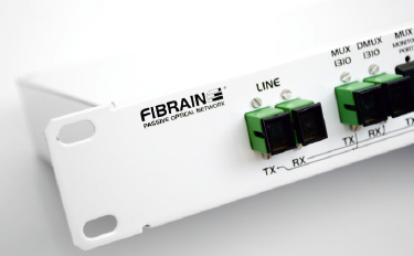
The CWDM overlay system designed by Fibrain allows optimally using the whole available bandwidth of the G.652D fiber while minimizing the investment and operation costs. The system contains passive optical multiplexers (central and outer) and CWDM SFP modules compatible with GPON transmission.
Advantages of Fibrain CWDM overlay system:
- Up to 8 CWDM channels and GPON channels transmitted in one optical fiber
- Full utilization of the standard optical fiber transmission band
- Low insertion losses that allow optimally using the available power budget
- Passive optical multiplexers operating in outdoor conditions (from -25°C to +70°C), making network planning and maintenance easier
- Fiber-optic adapters with built-in shutters that increase optical safety
- Central multiplexers with built-in bidirectional power monitoring ports, which facilitate service launching and network maintenance
- Two topology versions (A and B) of the CWDM overlay available
- Compatible SFP, SFP+, and XFP CWDM modules with large power budget and stable wavelength
Version A of the CWDM overlay system:
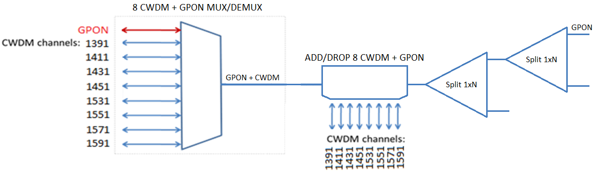
Fig. 1. CWDM overlay, version A – typical scheme of CWDM overlay aplication on GPON.
In version A, a passive central device allows multiplexing and demultiplexing of GPON and CWDM signals. In a standard solution, the central device is built into a 19’’ 1HU patch panel, but adjusting to customer’s requirements is possible. Besides the transmission ports, two 1% power monitoring ports for upstream and downstream directions are also routed, which facilitates service launching and network maintenance.
An analogous device is placed in front of the optical splitter and allows the access to CWDM channels before they propagate through the splitter. Therefore, the link losses seen by the CWDM channels are minimized, which increases the power budget for the CWDM transmission. The outer multiplexing device is adapted for operation in temperatures from 25°C to +70°C.
All optical ports are equipped with SC APC adapters with internal metal shutters, which increase optical safety.
Main advantages of version A of the CWDM overlay:
- Negligible effects on GPON power budget: the GPON power budget while using the CWDM overlay multiplexers is typically decreased by 2.8 dB
- No effect of optical splitters on the CWDM transmission power budget
Version B of the CWDM overlay system:
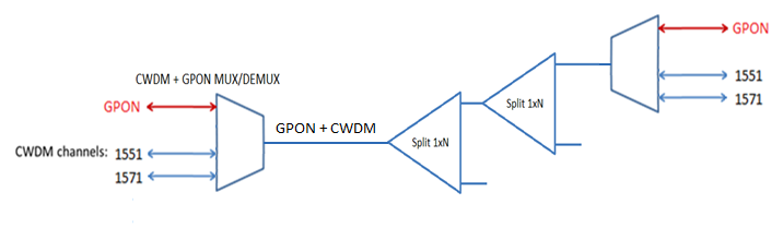
Fig. 2. CWDM overlay, version B – typical scheme of CWDM overlay aplication on GPON.
In version B, the passive central device that allows multiplexing and demultiplexing GPON and CWDM signals is identical to the one in version A. The outer multiplexers are placed behind the optical splitter (or cascaded splitters). Therefore, the same optical fiber reaching the subscriber can be used to construct GPON or CWDM transmission or both at the same time.
Main advantages of version B of the CWDM overlay:
- One fiber on the whole link length from the central to the final device – capability of bringing both GPON and CWDM to the subscriber simultaneously
- CWDM network power budget decreased typically by 2.8 dB (without taking into account losses due to CWDM channels multiplexing)
- Optical Transmission Lexicon: CATV, CWDM, DWDM, FTTH
- PON Technology-Based FTTH Networks for GPON Transmission
- FTTH Networks in Rural Areas and Sparse Housing Conditions
- CATV in FTTH networks
- CWDM Overlay for GPON Networks
- Passive CWDM Solutions
- Passive DWDM solutions
- Multimode GPON Transmission System
- Multimode CWDM Transmission
- Selective Wavelength Filters for Applications in Next Generation Access Networks