In most countries, the dominating technology for building optical access networks are passive optical networks (PONs). In such networks, the only active devices used are the optical line terminations (OLTs) located at the operator’s end and optical network terminations (ONTs) or optical network units (ONUs). The most popular currently used transmission standard in PONs is the GPON (Gigabit PON) defined by the International Telecommunication Union in G-984 recommendations.
In the GPON standard, the wavelength band of 1480-1500 nm is used for transmitting the signal from the OLT to ONU (downstream), and 1290-1330 nm (formerly 1260-1360 nm) band is used in opposite direction. This is of course a simple form of wavelength division multiplexing (WDM). Data in GPON can be transmitted with a symmetrical capacity of 2.5 Gbps/2.5 Gbps, but usually the available bandwidth is asymmetrical: 2.5 Gbps downstream and 1.25 Gbps upstream. The available capacity can be divided among up to 128 subscribers. The maximal distance between OLT and ONU is 60 km, whereas the distance difference between ONUs connected to the same OLT port (so called network range) cannot exceed 20 km. In GPONs, the typical power budget is 28 dBm (B+ class), and can be increased up to 32 dBm (C+ class) by using special lasers. Lasers and filters indispensable for building GPONs do not require high wavelength stability and are relatively easily accessible in the market. Alternative transmission protocol in PONs is the GEPON (defined by the IEEE in 802.3ah standard). Although it has significant limitations from the point of view of the operator (including much lower birate and less manegement capabilities), from the optical point of view (network topology and requirements for medium of transmission) it is very similar, therefore the solution for optical layer described in this article is fully compatible with the GEPON transmission.
Typically GPONs are built based on singlemode fibers and only this medium is allowed in the ITU-T recommendations and is supported by active GPON devices. More and more Internet users, especially ones that move into new buildings, expect the availability of ultrafast, ultrareliable, and ultrafashionable fiber optic Internet, which implies GPON (or sometimes GEPON). However, it could happen that in a multi-family or public facility building, which the demanding Internet user has just moved into, and in which an operator would like to launch a passive optical network, the building’s developer has already installed cables with multimode fibers. This is most likely to happen in high standard buildings, which means there would be many high value potential subscribers. Why in such buildings in particular? Currently, the costs of standard OM2 multimode fiber based cables are about twice higher than the costs of similar cables with singlemode fibers (and cables with OM3 fibers are even more expensive). Thus, every self-respecting developer assumes that if something is more expensive, it must be better, and doesn’t save money on equipping such building. Apart from this fact, it is much less pricey to use the existing infrastructure in the building than laying new singlemode fibers.
Unfortunately, as mentioned above, until now a telecommunication operator who wanted to supply their service in such multimode cabled building was drawn away by technical questions – they could not launch PON (GPON, EPON) on multimode fibers. In this case using standard solutions available in the market would not ensure a stable and faultless transmission. This is mostly due to the fact that a new phenomenon, modal dispersion, is present in multimode fiber that strongly degrades the signal quality. Its presence typically causes unacceptable BER increase and consequently transmission turnoffs. In addition, signal losses on the singlemode-multimode connection are so high they “kill” the power budget (value of these losses depends on modal excitation, and is of the order of 17 dB for LED excitation). Until now the only solution was laying a new, parallel singlemode network. To help operators avoid the costly change of cables, Fibrain company has developed and implemented the first passive multimode GPON transmission system in the market.
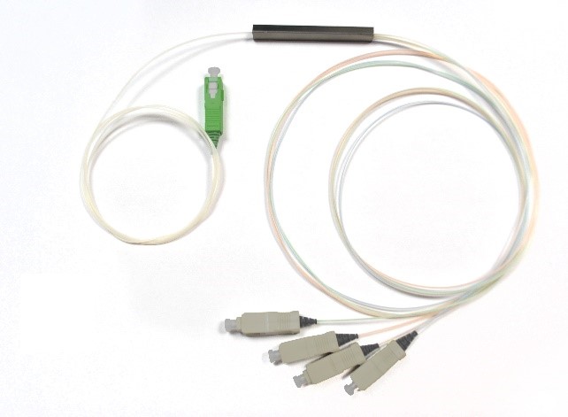
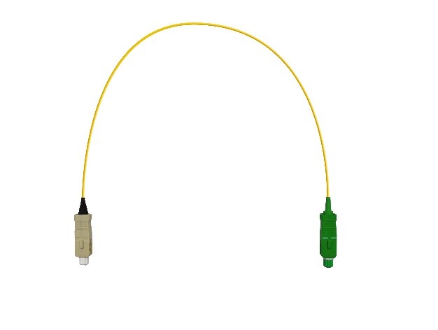
The passive multimode GPON transmission system contains a hybrid SM/MM splitter with a singlemode input and multimode outputs (Fig. 1a) and hybrid MM/SM patchcords (Fig. 1b). Using both the hybrid splitter and hybrid patchcords is necessary for correct system operation. The hybrid patchcords are used at the subscriber end for connection between the (multimode) network outlet with optical port in ONU/ONT subscriber device (always singlemode). The input singlemode end of the splitter (to be connected to the line cable) is terminated with an SC/APC connector, which is a standard connector used in GPON networks. The multimode splitter outputs (to be connected to the multimode inter-building distribution network) are terminated with SC/UPC connectors, which are common in networks based on multimode fibers. The hybrid patchcords are equipped with the same connectors, meaning SC/UPC at the multimode end and SC/APC at the singlemode end (to be connected to the active device). A visual scheme of connecting the inter-building multimode network with external singlemode GPON and ONU/ONT active devices is shown in Fig. 2.


Fig. 1. Multimode GPON transmission system components: a) Hybrid SM/MM splitter, b) Hybrid MM/SM patchcord


Fig. 2. Scheme of connecting an inter-building multimode network with external singlemode GPON and ONU/ONT active devices
From the operator perspective, the usage or installation of the passive multimode system is no different than for the standard singlemode system (even the connectors are hard to be confused thanks to color coding). Fibrain advises the use of the hybrid SM/MM transmission system with Dasan Networks GPON active devices, which are fully tested for compatibility with the system.
The passive multimode GPON system supports 2 gbps transmission over fibers with 50 μm core diameter (OM2, OM3, and OM4 standards) over a distance of 600 m. This distance exceeds the length of links in buildings. The solution has been tested for connection stability (transmission errors) in conditions of temperature changes from ‑40 to +85 °C (according to the IEC 61300-2-22 standard). The system works faultlessly also in high humidity conditions. It can be used not only inside buildings, but also outdoors.
If you are interested in more technical details please contact your sales support or drop us an email at info@fibrain.com.
TECHNICAL SPECIFICATIONS:
- Optical Transmission Lexicon: CATV, CWDM, DWDM, FTTH
- PON Technology-Based FTTH Networks for GPON Transmission
- FTTH Networks in Rural Areas and Sparse Housing Conditions
- CATV in FTTH networks
- CWDM Overlay for GPON Networks
- Passive CWDM Solutions
- Passive DWDM solutions
- Multimode GPON Transmission System
- Multimode CWDM Transmission
- Selective Wavelength Filters for Applications in Next Generation Access Networks
