10G-EPON – the IEEE 802.3av standard that defines fiber-optic new generation access networks, the successor of the IEEE 802.3ah (GEPON) standard. It has two versions: symmetrical (10Gbit in both directions) and asymmetrical (10Gbit/1Gbit). The standard uses wavelengths similar to XG-PON.
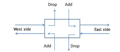
Add/drop filter – filter that allows for local separation (termination) of selected channels from the optical multiplex and local addition of new optical channels. They are used for building intermediate nodes in optical networks between the end nodes (terminals). Besides terminating and adding new channels, a drop and continue topology is also possible. The topology is used to achieve optical broadcast. Add/drop filters can be manufactured in WDM, CWDM, DWDM, or hybrid methods. They are basic building blocks of the FOADM node.
APC (Angled Physical Contact) – a standard of fiber-optic connectors with the ferrule endface polished at an angle of usually 8 degrees, sometimes also 9 degrees. The biggest advantage of angled polishing is a much better return loss, or much lower power reflected from such a connector (both closed and open).
APD (Avalanche Photodiode) – one of two main types of detectors used in optical telecommunication (the second one is the PIN diode). Its build-in mechanism of avalanche gain allows the diode to have a higher sensitivity, but adds avalanche noise. For example typical 10G detectors with an APN usually have sensitivity of about -24 dBm.
ASE (Amplified Spontaneous Emission) – an optical noise generated by all optical amplifiers (including Raman, EDFA, YEDFA, SOA). It lowers the optical signal-to-noise ratio (OSNR) in optically regenerated links. It is a consequence of appearance of spontaneous emission in every optical amplifier which always accompanies the desired stimulated emission. The amount of noise produced by an amplifier is quantified by its noise figure (NF)..jpg)
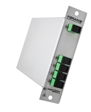
Asymmetrical splitter – any optical power splitter with N output ports, which by design carry different percentage of the input power. In the most often used version, an asymmetrical splitter has one high power output port (dubbed the express port) and the remaining N-1 ports (local ports) are nominally the same, with low percentage of input power. Alternatively, splitters with single very low power output port (used for monitoring purposes) are also encountered. It should be noticed that in practice due to technological reasons the attenuation of output ports in symmetrical splitters is also slightly different for each port (it is a so-called attenuation uniformity), but it doesn’t make the splitter asymmetrical. An example of an asymmetrical Fibrain PLC 1x5 splitter is shown below.
Attenuation – optical insertion loss.
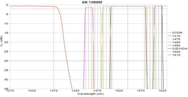
Attenuation spectral profile – a graph depicting dependence of attenuation on wavelength for an optical device (for example an optical splitter or a multiplexer). It is a way of presenting the whole information about spectral characteristics of this component, e.g. about maximal attenuation, attenuation uniformity, channel isolation, passband ripple, etc. The measurement of attenuation spectral profile requires using a wideband light source and an optical spectrum analyzer or a single-mode tunable laser. Only test reports that show the whole spectral profile of components (especially filters and multiplexers) show reliable worst cases of attenuation and isolation on which link design should be based.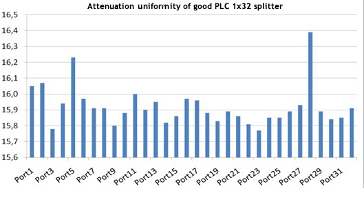
Attenuation uniformity – one of the basic parameters describing the quality of multiport passive optical devices, e.g. PLC splitters or xWDM multiplexers. It is a difference between the attenuation of the output port with the highest attenuation and the output port with the lowest attenuation, expressed in dB. Generally, it is desired (e.g. in nominally symmetrical PLC splitters) that this difference be as small as possible (close to 0 dB). The commonly used Telcordia GR1209CORE standard recommends that the uniformity be not worse than U [dB]= 0.6log2N, which means for example 3 dB of allowed attenuation difference among output ports of a 1x32 splitter. Such high differences would in practice complicate power budget calculations as well as network maintenance and troubleshooting. Because of this, good PLC splitters have attenuation uniformity similar to the one shown in the graph below. Attenuation uniformity is an essential, although often unappreciated, splitter quality metric, and one of the most important factors in distinguishing high quality manufacturers.
AWG (Arrayed Waveguide Grating) – a technology used to make multiplexers and demultiplexers with a high number of channels. It is a highly integrated planar technology that uses multibeam interference among many beams with a controlled phase difference. AWG multiplexers are used mostly in DWDM transmission, but Fibrain offers also AWG CWDM gratings. They are parallel filters with a high attenuation uniformity. For DWDM version they are usually available in versions with 40 or 44 channels on the 100 GHz grid, but 50 GHz is also available.
BER (Bit Error Rate) – defines the number of detected corrupted bits relative to the total number of detected bits. The lower the BER, the better the transmission quality. The BER is usually given in the 1e-X notation, e.g. a signal of operator quality is usually considered to have BER of at most 1e-12, which means on average one corrupted bit per every 10^12 bits of data. In the case of transmission in noisy channels (such as long DWDM links, satellite transmission), the BER at the channel output may be much worse (so-called pre-FEC error rate). The receiver (with a decoder) is able to retrieve the corrupted bits by using FEC correction codes, so the error rate at the decoder output (post-FEC) is much better.
BKtel Communications – a renowned German manufacturer of optical equipment for CATV, DPON, RFoG, and HFC networks, including optical transmitters for 1310 and 1550 nm with external and direct modulation, optical amplifiers EDFA and YEDFA, or detectors of feedback channel.
Booster – power amplifier. In optical telecommunications, an optical amplifier, usually of high power, used before injecting the signal into the fiber span.
C-band– or third transmission window. The ‘C’ symbol is short for Conventional.
CATV – historically an abbreviation for ‘Common antenna television’, today often used to describe the technology of delivering television service in access networks (HFC or PON/FTTH) with 1310 nm or 1550 nm transmitters. The standard RF band for CATV is 860 MHz, transmission in the 1 GHz is also used due to growing demand for bandwidth.
CFP (C Form-Factor Pluggable) - a compact transceiver used to transmit data, voice, or image with a rate of 40 or 100 Gbit/s. It is produced according to the MSA (Multi-Source Agreement) specification. ‘C’ stands for 100 (‘Centum’ in Latin). The standard was developed for 100 Gigabit Ethernet systems and can be also used for other high speed transmission systems. The design of the transceiver is similar to the SFP. CFP modules are supplied with a DDM (Digital Diagnostic Monitor) functionality. It allows monitoring the key parameters of module operation, such as optical power of transmitted signal, optical power of received signal, temperature of operation, power supply voltage, and laser current.
Channel grid – also called a raster. Optical channel separation in the optical multiplex in a WDM transmission that is defined in an adequate standard. In CWDM transmission, 20 nm grid is used and 18 channels are available (G.694.2 ‘Spectral grids for WDM applications: CWDM wavelength grid’). In DWDM transmission (G.694.1 ‘Spectral grids for WDM applications: DWDM wavelength grid’), 50 GHz and 100 GHz grids are most frequently used, but sometimes also 200 GHz and 25 GHz. The available number of channels in DWDM transmission depends on the grid used, for example for the 50 GHz grid it can be even 96 channels in the C-band. The gridless functionality, which is starting to appear in DWDM networks, means a possibility of composing channels of any width (unrestricted by channel separation) from the basic 12.5 GHz spectral blocks. It is used to save the optical spectrum during transmission of signals with significantly different in spectral widths, e.g. 10G and 400G, in one multiplex.
Chirp (of wavelength) – change of central wavelength within the impulse (bit). Can be caused for example by transmitter imperfections (in the case of directly modulated transmitters it results from the dependence of the refractive index in the laser cavity on the electrical current) or is an effect of chromatic dispersion in optical fiber.
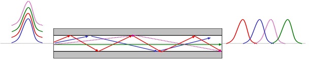
Chromatic dispersion – a property of op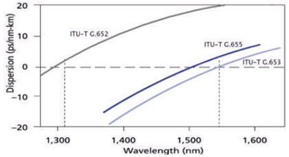 tical fibers that causes different signal velocities depending on the wavelength (frequency). It is directly caused by the dependence of refractive index on wavelength. Due to chromatic dispersion, the initially compact impulse spreads and disperses when propagating in fiber. The larger the propagation length and the wider the signal bandwidth, the faster the spreading occurs. The dispersed impulse “leaks” to neighboring bit slots, causing transmission errors at the receiver. Chromatic dispersion usually must be taken into account for 10G and faster signals. In long links it is compensated with DCMs (dispersion compensating modules).
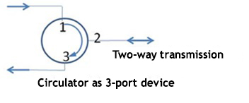 Circulator – a passive optical device (usually 3-port, also 4-port) with a specified directivity, i.e. it directs the input signal to a specified output port depending on the input port. In the 3-port circulators, transmission occurs between ports 1-2 and 2-3. Between the other port pairs, directional isolation occurs (the higher the better). Circulators are most often used to connect parts of a link in which single fiber is used for bidirectional transmission with parts with unidirectional transmission over a pair of fibers (in each of the fibers in one direction only).
CNR (Carrier to Noise Ratio) – a basic measure of analog optical signal quality. In TV signal, it is the ratio of RF carrier amplitude to noise amplitude, usually expressed in dB or dBmV. The higher the CNR, the better the transmission quality.
CSO (Composite Second Order) – the difference (usually measured in dB) between the carrier amplitude and composite second-order distortions. It is often expressed in dBc units, where ‘c’ means that it is measured relatively to the carrier level. The higher the difference the better. CSO distortions can be caused by transmitter imperfections (nonlinear dependence of optical power on the drive current, too large OMI), or by transmission effects, such as chirp and chromatic dispersion.
CTB (Composite Triple Beat) – the difference (usually measured in dB) between the carrier amplitude and composite third-order distortions. It is often expressed in dBc units, where ‘c’ means that it is measured relatively to the carrier level. The higher the difference the better. CTB distortions can be caused by transmitter imperfections (nonlinear dependence of optical power on the drive current, too large OMI) or RF amplifiers imperfections.
CWDM (Coarse Wavelength Division Multiplexing) – a technique of multiplexing in the wavelength domain, used in fiber-optic transmission. The two most important ITU-T recommendations that define the CWDM technique are the G.694.2 (Spectral grids for WDM applications: CWDM wavelength grid) and the G.695 (Optical interfaces for coarse wavelength division multiplexing applications). The G.694.2 recommendation defines 18 CWDM channels, from 1271 nm to 1611 nm, with channel separation of 20 nm. Traditionally, 1371 nm and 1391 nm channels were rarely used due to the so-called water peak in old-type optical fibers. Today, the quality of G.652.D standard fibers allows for exploitation of all 18 CWDM channels. In some cases, using the low channels (1271 nm and 1291 nm) may be problematic because some low-quality G.652.D fibers may not guarantee single-mode operation in this region. Using CWDM transmission in other types of single-mode fibers (e.g. G.655) requires caution because not all CWDM channels may be supported due to dispersion properties, spectral profile, or cutoff wavelength.
CWDM meter – a type of optical power meter that allows the power measurement of all 18 CWDM channels. It is used during the installation and link troubleshooting. It differs from the standard optical power meters in that it is calibrated for all CWDM channels and has built-in optical filters, which allow for identification and measurement of individual CWDM channels in the measured optical multiplex. It is typically connected directly to the line cable or to the power monitoring port on an optical multiplexer/demultiplexer. An example of a CWDM meter is the Fibrain FCPM-18/1310.
CXP - a transceiver format used in optical telecommunications with a rate of at most 12×10 Gbit/s. ‘C’ stands for 100 (‘Centum’ in Latin), and is used in the name because the transceiver can support 100 Gbit/s transmission. According to other sources, ‘C’ stands for 12 in hexadecimal number system, and 'X' the Roman numeral for 10. The transceiver is hot pluggable, has LC type optical connectors, and is slightly larger than the XFP. The standard was developed for use in high density short reach applications in data centers.
DCF (Dispersion Compensating Fiber) – an optical fiber that compensates chromatic dispersion. Using a DCF is one of the methods of DCM production. To compensate dispersion effectively, the chromatic dispersion coefficient of the DCF must be an inverse of the chromatic dispersion coefficient of the transmission fiber and their dispersion slopes must be as close as possible (that is an inverted spectral profile of chromatic dispersion).
DCM (Dispersion Compensating Module) – a module for compensating chromatic dispersion. They are usually produced with a DCF or FBGs. Using DCMs eliminates the destructive effect of chromatic dispersion on optical signal quality.
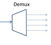 Demultiplexer (demux) – a device that terminates a part of a link common to a group of channels. From the demultiplexing point, individual channels propagate separately. The demultiplexer splits channels from an optical multiplex input to to its dedicated line output ports. Optical demultiplexers can be produced in WDM, CWDM, DWDM or hybrid technologies.
DFB (Distributed Feedback Laser) – in this type of semiconductor laser, instead of “solid” mirrors on both ends of the laser cavity (like in Fabry-Perot lasers), a periodic structure that creates a diffraction grating is used. Effective mirrors created in this way have a high wavelength selectivity which enables single-mode operation (longitudinal laser modes) of the DFB lasers.
Direct modulation – modulation of laser power by modulating the drive current. Comparing to the alternative external modulation, the output optical signal has worse quality. This is caused by the nonlinear characteristics of optical power vs. current (which is important particularly in CATV networks) and central wave chirp. The chirp occurs because material refractive index is dependent on the current density. CATV 1550 nm transmitters with direct modulation have much shorter ranges than transmitters with external modulation.
DPON (Docsis PON) – access network architecture in which the transmission medium is optical fiber in the PON topology (with multi-access by time division), with a centrally located optical splitter, and the communication protocol is Docsis. The DPON architecture is advocated by many traditional HFC/CATV suppliers as a transition phase for cable operators before implementation of GPON or similar protocols. The DPON inherits all the disadvantages of Docsis in HFC, mostly the limited and highly asymmetrical band. It offers typical advantages of a fiber-optic medium such as low losses (long range), low failure rates, and network operating costs. RFoG is often used as a synonymic term.
DWDM (Dense Wavelength Division Multiplexing) – a method of multiplexing in the wavelength domain, used in fiber-optic transmission. The most important ITU-T recommendations that define the DWDM method are the G.694.1 (Spectral grids for WDM applications: DWDM wavelength grid), the G.692 (Optical interfaces for multichannel systems with optical amplifiers), the G.698.1 (Multichannel DWDM applications with single-channel optical interfaces), and the G.698.2 (Amplified multichannel dense wavelength division multiplexing applications with single channel optical interfaces). The G.694.1 recommendation defines alternative DWDM channel grids with 12.5 GHz, 25 GHz, 50 GHz, 100 GHz (and consequently coarser grids) channel separation. The central wavelengths are defined relatively to the 193.1 THz anchor frequency. Besides the specified channel grids, the newest version of the G.694.1 recommendation introduces the term of flex grid, in which the width of each channel can be any multiple of 12.5 GHz. The flex grid was introduced to improve the spectral effectiveness of systems, in which signals with narrow spectrum (e.g. 10G) are transmitted together with signals with wide spectrum (e.g. 100G). Although there are no fundamental reasons that the DWDM transmission cannot take place in any transmission window, the C-band (around 1550 nm) is used in practice. This is due to the availability of EDFAs that operate in this range. DWDM systems for L-band can also be found, but they much more rarely used. The DWDM transmission is analog even when sending a digital signal, and optical design of DWDM links (especially long ones) must take into account a large number of signal quality degrading effects.
DWDM PON – optical access network architecture, in which the transmission medium in optical fiber. Like in typical PONs, a part of the link is shared, and the last section is dedicated to each subscriber. Unlike typical PONs (e.g. using the GPON or GEPON protocols), the central point in the DWDM network is a DWDM multiplexer (instead of an optical splitter). This allows for using wavelength division multiplexing instead of time division-based multi-access. Each subscriber receives a dedicated wavelength (more precisely a pair of DWDM channels, one for upstream and one for downstream transmission). The DWDM PON offers a very high capacity, but presently the costs are still too high for it to become widespread.
EDFA (Erbium Doped Fiber Amplifier) – a basic type of optical amplifiers used in optical telecommunications (e.g. in DWDM and CATV networks). Erbium amplifiers typically operate in the C-band (the third transmission window, 1525 – 1565 nm). The natural gain profile of erbium is very irregular, with a gain peak at about 1530 nm. Multichannel DWDM amplifiers have built-in gain-flattening filters (GFFs) to assure equal levels of power for each transmitted channel. EDFAs, like all other amplifiers, apart from the signal gain produce optical ASE noise that degrades the signal quality (lowers the OSNR). The availability of erbium amplifiers together with the fact that the glass optical fiber has minimal attenuation around 1550 nm were the main factors that caused the DWDM method to develop in the third transmission window. Besides the standard C-band EDFAs, erbium amplifiers for the L-band are also available, but they are much less popular, have worse parameters and higher prices. Optical amplifiers are also commonly called optical pumps.
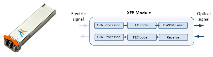
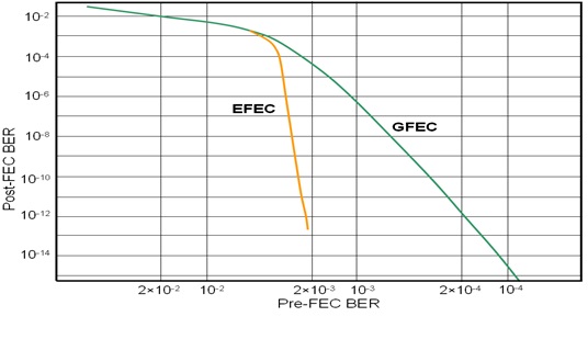
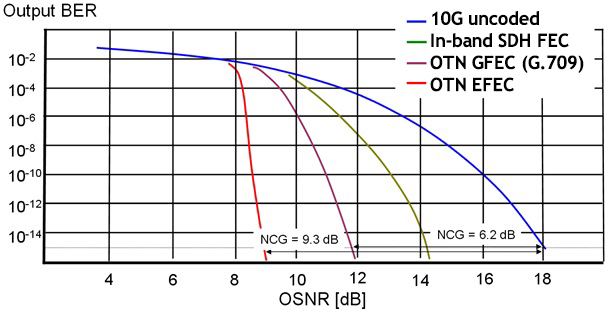 EFEC (Enhanced FEC) – permitted by the G.709 recommendation and used in OTN transmission improved FEC error correction codes with higher coding gain than standard GFEC. Generally, the EFEC codes are not standardized (although some are described in the G.975.1), so they cannot guarantee interoperation. The EFEC codes are the most effective in improving the signal’s resistance to noise (mostly thermal noise and ASE), which translates directly into OSNR budget improvement. The EFEC codes used in OTN 10G transmission have coding gain of about 8-9 dB (OSNR budget improvement). The codes to a small extent improve the resistance to distortions (e.g. chromatic dispersion). In traditional DWDM ONT networks, the FEC coder/decoder is placed on the DWDM transponder. In the IPoDWDM approach (represented e.g. by OTN quasi-transponders produced by Menara Networks), the coder/decoder is installed directly in the L2 or L3 layer network devices (in the case of Menara Networks quasi-transponders, integrated in MSA compliant XFP and SFP modules).
EPON (Ethernet PON) – see GPON.
ER (Extinction Ratio) – generally, it is a ratio of any signal parameter that can have two values. In optical telecommunications, it most frequently relates to the ratio of optical power in ‘1’ bit to optical power in ‘0’ bit in binary transmission. The higher the ratio the better the signal quality. When using transmitters with a low ER, the decrease of signal quality caused by this parameter is accounted in the connection design as a penalty.
External modulation – one of the two basic methods of optical transmitter modulation (the other one is direct modulation). In transmitters with external modulation, the laser operates in continuous wave mode, and a modulator located behind the laser is responsible for converting the electrical signal to optical domain. Transmitters with external modulation are more expensive than transmitters with direct modulation due to the necessity of using additional components (modulators). However, the signal quality of such a transmitter is much better (no chirp, better wavelength stability, and higher CNR, CSO, and CTB parameters). Transmitters with external modulation are used e.g. in CATV networks for difficult links (long, with high attenuation, with many optical amplifiers, etc.) or when working with YEDFAs. An example of a CATV transmitter with external modulation is the ES10XL produced by BKtel Communications.
Fabry-Perot lasers – a type of semiconductor lasers in which the feedback that is essential to laser action is provided by hard mirrors (that use Fresnel reflections), usually produced by cleaving semiconductor crystals. On the semiconductor-air boundary, Fresnel reflections occur due to the difference in refractive indices. Fresnel mirrors are broadband (without wavelength selectivity), which means that the FP lasers operate in many longitudinal modes (they are multimode unlike e.g. DFB lasers). Each longitudinal mode has different wavelength. The spectral separation between the modes is constant and results from the constant width of the resonance cavity. The total power of the FP laser is essentially constant, but the power of each mode fluctuates. From the practical point of view it means that when chromatic dispersion is present during transmission, an additional noise appears (so-called MPN – mode partition noise). Due to this noise, the F-P lasers are mostly used in the 1310 nm window. When using a 1550 nm transmission, very short transmission lengths can be achieved.
FBG (Fiber Bragg Grating) – reflects some wavelengths by periodic structures imprinted along the fiber length. In optical telecommunications they are sometimes used for building multiplexers, but mostly as one of the two main technologies for producing chromatic dispersion compensators as well as GFFs.
FBT (Fused Biconical Tapering) – a monolithic technology for producing fiber-optic couplers (or splitters). It is based on high-temperature longitudinal fusing of a certain number of optical fibers, and then stretching the resulting bundle. As a result of the narrowing, the optical power leaks from the primary fiber and is coupled into the secondary cores, creating a coupler. The process can be stopped at any moment, so any coupling ratio can be achieved. An advantage of the FTB technology as a monolithic technology are also very low excess losses (below 0.1 dB). FBT couplers can be wideband like PLC splitters (when using an adequate manufacturing technology). Besides power couplers, WDM couplers can be also produced using (slightly modified) FBT technology. Fibrain is one of a few European manufacturers of FBT couplers.
FBT coupler – an optical power splitter produced in the FBT technology. Can be manufactured as asymmetrical or symmetrical splitters.
FEC (Forward Error Correction) – error correction codes used in telecommunications. By employing them, the receiver/decoder is able to fix corrupted bits, using additional information contained in the FEC fields (inband or out of band). In optical telecommunications, FEC inband coding with relatively low coding gain is possible in SDH transmission. In OTN transmission a special FEC 4x256 field is added to the frame (behind ODU), so this FEC is out of band. Coding gain of FEC codes used in ONT networks is much greater than for the codes used in SDH, which translates mostly into much greater resistance of the signal to optical ASE noise (larger OSNR budget), so to reaching large optically regenerated link lengths. Using effective FEC codes allowed for popularization of transparent optical networks. In traditional DWDM OTN networks, the FEC coder/decoder is placed on a DWDM transponder. In the IPoDWDM approach (represented e.g. by OTN quasi-transponders produced by Menara Networks), the coder/decoder is built-in directly into the L2 or L3 layer network devices (in the case of Menara Networks quasi-transponders, integrated in MSA compliant SFP or XFP modules).
Fibrain – a Polish company and brand of passive devices used in fiber-optic telecommunications, fiber-optic cables, and equipment and passive infrastructure for optical networks. Today, the manufacturer owns three production facilities near Rzeszow (including one of the most modern fiber-optic cable factories in Europe).The company is the largest in the industry in Poland and has a worldwide presence, most notably in all Europe, Middle East and North Africa or Latin America.

 FOADM (Fixed Optical Add/Drop Multiplexer) – a type of optical network node that allows for local separation (termination) of selected channels from the optical multiplex and local addition of new optical channels. It is a network node of at least second order (connected to at least two lines). In the case of the most frequently used FOADM second order nodes, it can be single-sided (with possibility to set up connection to optical nodes on one line) or dual-sided (allows setting up the connections to other optical nodes on both lines). The term ‘fixed’ means that the wavelengths terminated in the FOADM node are predetermined and limited by the filters used. Any change of traffic matrix requires a physical local intervention and re-cabling. The basic components of FOADM node construction are add/drop filters. FOADM nodes can be produced in WDM, CWDM, DWDM, or hybrid technologies.
FTTH (Fiber To The Home) – a type of optical access network, in which the optical fiber is supplied to the subscriber’s place of residence, where the ONT customer terminal with a line optical port is located. FTTH networks can be built in the Active Ethernet topology, in which each subscriber has their own dedicated fiber on the whole length from the central hub to the subscriber, or in the PON topology, in which the main fiber is common for all subscribers within one network segment, and the dedicated subscriber fiber is used only for the section from a splitter to the subscriber. In the PON topology, a multi-access with time division (usually the GPON or GEPON protocols) is used. DWDM PONs have PON physical topology, while the logical topology is Active Ethernet. Nowadays, FTTH networks are the most modern approach to access network construction and offer capacities inaccessible in other technologies. In practice, although each subscriber in a PON transmits only in a dedicated time slot, because of the uplinks restrictions, the effective capacities achieved in the PON and Active Ethernet networks are the same.
FTTx (Fiber To The X) –X can be B – building, C – curb/cabinet, D – desk, H – home. A general name for access networks, in which the basic transmission medium is optical fiber. Depending on the point where the optical medium ends and possibly a copper medium starts, different versions of FTTx are distinguished. FTTx networks are classified as new generation access networks (NGA).
FWM (Four Wave Mixing) – one of nonlinear phenomena in optical fibers that result from the Kerr effect. As a result of the FWM process, after an interaction of three initial waves a new fourth wavelength is formed. If the newly created wave has the same frequency as one of the usable channels, the channel is disturbed and its transmission quality decreases. The effectiveness of the FWM process depends on the link length, optical power, amount of chromatic dispersion and separation between channels. The G.653 fiber that has zero dispersion in the C-band cannot be used for multichannel DWDM transmission for this reason.
G.652 – the G.652 single-mode fiber was defined in the ITU G.652 recommendation (Characteristics of a single-mode optical fibre and cable). It is the basic and oldest standard of a single-mode fiber. There are four subtypes of fiber in this standard: A, B, C, and D, of which A is the oldest, and D the newest (current). The A and B versions do not define the height of the 1383 nm water peak, unlike the C and D versions (with reduced and controlled water peak). The B and D versions have better values of the PMD parameter (polarization mode dispersion index). The most important parameters of the G.652 fiber are:
- Zero chromatic dispersion around 1300-1324 nm,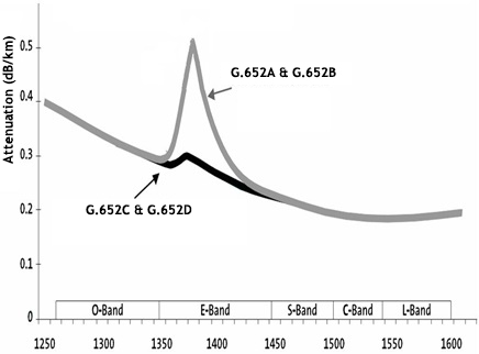
- Max. attenuation 0.4dB/km @1310nm, 0.3dB/km @ 1550nm (a little more in the A and B versions),
- Chromatic dispersion 17 ps/km/nm @1550 (in the standard defined via the dispersion slope),
- Min. bending radius 30 mm,
- Max. cutoff wavelength 1260 nm,
- Mode field diameter 8.5-9.5 um.
G.653 – the G.653 (DSF) single-mode fiber was defined in the ITU G.653 recommendation (Characteristics of a dispersion-shifted single-mode optical fibre and cable). The fiber is currently rarely encountered, and not produced anymore because it didn’t turn out to be universal – it was useful only for single-channel transmission in the C-band. It couldn’t be used in multichannel DWDM transmission due to very large nonlinearities that were caused by very low values of chromatic dispersion in the C-band (nominally 1550 nm had zero dispersion). Defined were two versions of the G.653 standard: A and B. The B version has better values of the PMD parameter. The most important parameters of the G.653 fiber are:
- Max. attenuation 0.35 dB/km @1550 nm (typ. 0.275dB/km, not defined for 1310 nm),
- Min. bending radius 30 mm,
- Max. cutoff wavelength 1270 nm,
- Mode field diameter 7.8-8.5 um.
G.654 – the G.654 (CSF) single-mode fiber was defined in the ITU G.654 recommendation (Characteristics of a cut-off shifted single-mode optical fibre and cable). It is a fiber with zero dispersion at around 1310 nm, shifted cut-off wavelength, and minimized losses in the 1530-1625 nm band. Fibers of this type are rarely seen, mostly because they are not universal – optimized for very long-distance DWDM transmission, they cannot be used for CWDM transmission. Technologically, the G.654 fiber has a core made of undoped glass (the cladding is doped) and with a larger radius, which translates to low losses and smaller nonlinearity. The most important parameters of the G.654 fiber are:
- Max. attenuation 0.22 dB/km @1550nm (practically of the order of 0.17 dB/km, not defined for 1310 nm),
- Chromatic dispersion 20 ps/nm/km @1550 nm,
-Max. cutoff wavelength 1530 nm,
- Mode field diameter 9.5-10.5 um (@1550nm).
G.655 – the G.655 (NZ DSF) single-mode fiber was defined in the ITU G.655 recommendation (Characteristics of a non-zero dispersion-shifted single-mode optical fibre and cable). It is a fiber with shifted chromatic dispersion characteristic (small, but nonzero dispersion around 1550 nm). Introducing a small amount of chromatic dispersion in the third transmission window was decided on due to very high nonlinearity observed in the G.653 fiber with zero chromatic dispersion. The G.555 fiber is in practice quite frequently encountered although it has limited applications. The restricted universality results from the fact that as the fiber is optimized for DWDM transmission, it can be problematic when used for CWDM transmission due to high cutoff wavelength. The G.655 fiber can have positive or negative chromatic dispersion. Segments of fiber with negative dispersion can be used in metro networks for transmission and compensation simultaneously. Since the fiber has low values of chromatic dispersion, longer links than in the case of the G.652 fiber are possible without the need for chromatic dispersion compensation in connections with high bitrates. Five versions of the standard - A, B, C, D, and E - were defined. They differ (significantly) in the chromatic dispersion profile. The most important parameters of the G.655 fiber are:
- Max. attenuation 0.35 dB/km @1550 nm,
- Dispersion 4-10 ps/nm/km @1550nm,
- Max. cutoff wavelength 1450nm,
- Mode field diameter 8-11 mm (in practice can be less than the standard requirements).
G.656 – the G. 656 (WB NZ DSF) single-mode fiber was defined in the ITU G.656 recommendation (Characteristics of a fibre and cable with non-zero dispersion for wideband optical transport). It is a fiber with shifted dispersion characteristic (low, but nonzero dispersion). Fundamentally, it is an extension of the G.655 standard that guarantees a wider range of applications. The fiber is very rarely encountered because the standard is relatively new (adopted only in 2004). The G.656 fiber is optimized for DWDM transmission, but should also support CWDM transmission. The cutoff wavelength is large enough to guarantee single-mode operation in the S, C, and L bands only. Chromatic dispersion of the G.656 fiber was specified in the 1460-1625 nm range (S, C, and L bands). The most important parameters of the G.656 fiber are:
- Max. attenuation 0.35 dB/km @1550 nm,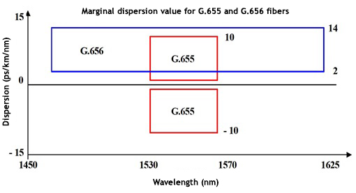
- Dispersion 2-14 ps/nm/km (in the range of 1460-1625 nm),
- Max. cutoff wavelength 1450 nm,
- Mode field diameter 7-11 mm.
G.657 – the G. 657 single-mode fiber was defined in the ITU G.657 recommendation (Characteristics of a bending loss insensitive single mode optical fibre and cable for the access network). It is a fiber dedicated to access networks, with a reduced allowed bending radius and reduced bending losses. It is more frequently seen and rapidly gains popularity, usually in PON/FTTH networks for which it was designed. The first version of the standard specified two versions (A and B, unofficially there was also B+/C). The current version specifies four versions (A1, A2, B2, and B3) that differ mostly in the allowed bending radius and compatibility with the G.652 fiber. The Ax classes should be fully compatible with the G.652D, and the Bx classes not necessarily (mostly different mode field diameters, chromatic dispersion profiles, possible problems with splicing to G.652).
GFEC (Generic FEC) – a type of error correction FEC coding used in OTN networks, defined in the G.709 recommendation. It is a so-called RS (255, 239) interleaved Reed-Solomon code. Each framer compliant with the OTN standard must support this coding. This ensures interoperatibility among different OTN equipment providers. Usually, besides FEC coding, the framer supports also a second mode of operation, the so-called EFEC, but operation in this unstandardized mode doesn’t guarantee interoperatibility. By using the correction codes, the receiver/decoder is able to fix corrupted bits and improve the quality budget of a signal. GFEC coding, like the EFEC, improves the resistance of the signal to random distortions i.e. noise. In practice, the improvement of resistance to ASE optical noise (increasing the OSNR budget) is the most important, sometimes also the improvement of resistance to thermal noise (increasing the power budget). In traditional DWDM OTN networks, the FEC coder/decoder is placed on the DWDM transponder. In the IPoDWDM approach (represented e.g. by OTN quasi-transponders produced by Menara Networks), the coder/decoder is built-in directly into the L2 or L3 layer network devices (in the case of Menara Networks quasi-transponders, integrated in MSA compliant SFP or XFP modules).
GFF (Gain Flattening Filter) – a filter that flattens the gain profile of optical amplifiers (mostly EDFA), so that they can be applied in multichannel DWDM transmission. The natural gain profile of EDFAs (like of the Raman amplifiers) is very irregular, which causes different gain seen by each of the DWDM channels, and as a consequence burying the low-power channels in the optical noise and nonlinearities that would degrade channels with too high power. The GFFs are usually manufactured by using fiber Bragg gratings (FBGs) but also with long-period gratings (LPGs).
GEPON (Gigabit Ethernet Passive Optical Network) – the IEEE 802.3ah network standard in the point-to-multipoint topology. It offers a symmetrical capacity of 10Gbit, which is shared dynamically by active ONT terminals. This standard uses wavelengths similar to the GPON. Unlike the GPON standard the GEPON doesn’t offer built-in interoperability mechanisms.
GPON (Gigabit Passive Optical Network) – the ITU-T G.984.4 access network standard in the point-to-multipoint topology, created mostly for telecom operators who build FTTH networks. It offers an asymmetrical speed of 2488Mb/1244Mb, which is shared dynamically by active ONT terminals. The maximal split in GPON from one OLT device is 1:128, which means that there can be 128 subscriber outlets joined to one port on the concentrator. The used wavelengths are 1490nm/1310nm. The 1550 nm wavelength is reserved for the CATV.
HFC (Hybrid Coax/Fiber) – an access network architecture which uses the optical fiber in the feeder part and coaxial cable in the subscriber part. It is a technology used mostly by the cable operators (cabelco). In an HFC network, Triple Play services (internet, television, telephone) may be provided. The TV service is usually provided as DVB-C and analog PAL (although the HFC architecture is indifferent to the kind of TV modulation and providing e.g. DVB-T is encountered). The internet and telephone services (VoIP) are provided via the Docsis protocol. The central devices in an HFC network are a head station and CMTS as well as optical transmitters (1310 nm and 1550 nm, often with EDFAs), at the subscriber end the customer terminal is usually a cable modem. Since both upstream and downstream transmission must be carried in one coaxial cable, the available RF band must be divided into two blocks. The upstream band is usually from 5 MHz to 65 MHz, and the higher limit of the downstream band is 862 MHz or 1 GHz. The noticeable asymmetry is one of HFC network disadvantages that make it difficult to offer symmetrical connections required by many business customers. The coaxial part of the network, often with many RF amplifiers, can be the reason of many problems with reliability and loss of signal quality. This is why a trend visible for many years is to shorten the coaxial part and extend the fiber part, which results in a purely optical DPON/RFoG network, which from the infrastructure point of view is a version of FTTH PON.
Insertion loss (IL) – a measure of what part of optical power is lost during signal propagation through an optical component.
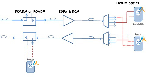 IPoDWDM (IP over DWDM) – an approach to building DWDM networks that assumes the integration of the L2 or L3 switching layers with the L1 transport layer. In traditional telecommunication network, the transport layer consists of dedicated DWDM OTN systems (or other standard of transport network) that allow for connections of L2/L3 layer devices (Ethernet switches, routers) to the network via the customer ports in ingress and egress points (transponders). Such an approach ensures the demarcation of signal, quality monitoring and management, but also translates to the necessity of maintaining two separate systems for network management and to high costs of the transport layer. In many cases, integrating the functionalities of the transport layer (mostly DWDM optics and OTN functionalities) directly into the L2/L3 layer devices seems attractive. One of the most interesting approaches to IPoDWDM networks was demonstrated by Menara Networks. The company offers so-called OTN quasi-transponders, or DWDM SFP, XFP and Xenpak modules compliant with appropriate MSA specifications, but also having a built-in OTN chip with a FEC decoder. The OTN quasi-transponder can be plugged into any network device with an appropriate port, like Ethernet switch or FibreChannel, router IP, etc. Hence the network device with plugged in quasi-transponders becomes an OTN device with all its advantages (mostly the DWDM laser and GFEC/EFEC coding that significantly improves the OSNR budget), without the need to use standalone OTN transponders, which significantly reduces the costs of building such a network.
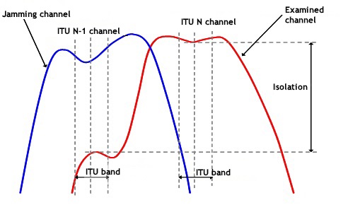 Isolation (in filters) – one of the basic parameters defining the quality of optical filters (demultiplexers, add/drop filters). Isolation defines how much power of the neighboring channels leaks into the examined channel measured at the dedicated channel output port in a filter. The lower this power (or the higher the isolation) the better, because power leaking causes signal degradation that lowers the signal quality. Due to passband ripple and a finite slope steepness, an accurate and reliable isolation measurement requires taking the worst case from the complete spectral profile of filter (demultiplexer) attenuation.
 LGX (Light Guide Crossconnect) – de facto a present industrial standard of modules and patch panels. The basic LGX module has 29x100 mm dimensions (WxH). The chassis that allows the vertical assembly of LGX modules has a height of 3 RU. A 3U 19’’ chassis can fit 14 such modules. On a single width front panel of the LGX, 10 SC SX adapters can be placed. In LGX modules, PLC splitters, FBT couplers, CWDM and DWDM multiplexers, circulators, etc. can be assembled.
Longitudinal laser modes – wavelengths supported by the laser’s resonance cavity (and by the material gain profile). Single-mode lasers (e.g. DFB) support only one wavelength and are used for CWDM and DWDM transmission. Multi-mode lasers (Fabry-Perot) emit light at 10-100 wavelengths at the same time and due to their very wide spectrum cannot be used for CWDM and DWDM transmission. An example of a two-mode laser spectrum is shown below.

LWPF (Low Water Peak Fiber) –optical fiber with a reduced water peak.
Menara Networks – an American manufacturer of CFP, SFP, XFP and Xenpak modules with a built-in ONT framer and FEC (EFEC and GFEC) coder, i.e. so-called OTN DWDM quasi-transponders. The OTN quasi-transponders may be used for building of IPoDWDM networks. They are available with a tunable or non-tunable laser. They are compatible with any network device (such as Ethernet switch, IP router, SDH crossconnect) that has suitable optical ports.
MFA (Mode Field Adapter) – a device used to connect two fibers with different core diameters and numerical apertures. Matching fiber mode fields is accomplished by thermally expanding the smaller fiber core or tapering the large core. Thanks to MFAs, the attenuation of a fiber splice can be decreased to below 0.5 dB. These devices usually can withstand high powers, which allows for using them in fiber lasers and amplifiers.
MMF (Multi Mode Fiber) – a type of optical fiber that supports a transmission of more than one mode. Comparing to the single-mode fiber (SMF), it has a larger core diameter. MMFs used in optical telecommunications can have a core of 62.5 mm diameter (fibers of the OM1 standard) or 50 mm diameter (OM2, OM3, and OM4). 850 nm (the so-called first transmission window) and 1300 nm (second transmission window) bands are used for transmission in MMFs. Due to modal dispersion, MMFs are used only in short links of length not exceeding a few km.
Modal (multimode, intermodal) dispersion – in a multimode fiber, each propagating mode (and there are usually hundreds of them) propagates with a different effective speed, which means that they appear at the output at different times, which in turn causes pulse spreading and transmission distortions. Because both the excited modes and the power in each mode change randomly (depending on the vibrations, mechanical stresses, temperature, light source characteristics, etc.), modal dispersion is a random and time-dependent phenomenon and today cannot be optically compensated. It is usually the basic mechanism that limits the length of multimode connections. Modal dispersion increases linearly with link length and transmission speed.
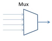 Multiplexer (mux) – a device that terminates a part of an optical link common to a group of channels. Individual channels propagate separately (on dedicated fibers) from their emitting lasers to the multiplexer. The multiplexer joins the incoming optical channels (wavelengths) creating an optical multiplex that is then led out on a common line port. Optical multiplexers can be produced in WDM, CWDM, DWDM, or hybrid technologies.
Muxponder – in optical transport systems, a device (usually a chassis card) that performs multiplexing operation of client electrical signals in time domain (TDM). The effect of muxponder operation is a line signal of a higher bitrate (equal to at least the sum of bitrates of the client signals). An example of a muxponder can be a device which multiplexes 2x 1GbE to the 2.5G stream. On the far end of the link, a receiving device performs an inverse operation, outputting elementary client signals on client ports. A muxponder is unable to shift data between client ports (a device capable of doing this is usually called an ADM). A muxponder is a type of transponder.
NG PON (Next Generation Passive Optical Networks) – general name for optical access networks allowing at least 10 Gbit/s transmission rate, successors to the currently dominant GPON standard. As of now the future of optical networks remains a bit unclear, both TDMA-based protocols like XG-PON1, XG-PON2 or XGS-PON are considered, as well as protocols utilizing additional multiplexing techniques, like TWDM PON or PtP WDM PON.
O-band – or second transmission window. The ‘O’ symbol is short for Original.
OADM (Optical Add/Drop Multiplexer) – a type of optical network node which enables local termination of some channels from a given optical multiplex and local addition of new optical channels to the outgoing multiplex. It is a network node of at least second order (i.e. connected to at least two lines). OADM nodes can be fixed (FOADM) or reconfigurable (ROADM). OADM nodes can be produced in WDM, CWDM, DWDM or hybrid technologies.
OLT (Optical Line Terminal) – an active device used in PONs to provide service to subscribers. The OLT coordinates signal multiplexing and multiple access (in GEPON and GPON networks TDMA access is used). It is usually centrally located and manages the remote ONTs/ONUs. In GEPON and GPON networks OLT transmits and receives over single fiber and each OLT port is connected to an optical splitter (e.g. PLC). Only after the splitter individual fibers are routed to each subscriber. In GPON standard each OLT port can have up to 128 subscribers connected through splitters.
ONT (Optical Network Terminal) – a subscriber terminal in FTTH networks in PON technology. Unlike the ONU, the ONT is usually designed for serving one family (Single Family Unit).
ONU (Optical Network Unit) – a subscriber terminal used as an MDU (multi dwelling unit) for operation in PONs in FTTB/FTTC topology, for example to aggregate traffic from whole apartment building.
Optical amplifier – an active device which provides optical gain, i.e. transparently increases the power of an optical signal without the need for its conversion to electrical form. Therefore, optical amplifiers are transparent for protocols and transmission rates. In practice, each optical amplifier besides increasing the desired optical signal power also produces optical ASE noise, which decreases the OSNR. Types of optical amplifiers used in fiber optic telecommunications are mostly EDFAs, but also the YEDFAs, Raman amplifiers, and SOAs (semiconductor optical amplifiers).
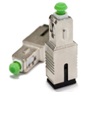 Optical attenuator – a passive optical device used for reducing excess optical power, e.g. for preventing a receiver from overloading. Fixed optical attenuators are usually made of high-loss fiber. They can be manufactured in inline and adapter forms. Fibrain optical attenuators are an example.
Optical loss – a part of optical power lost as a result of signal propagation through a given optical component. It is a ratio of the incident power to the output power (in linear scale i.e. mW). It is most often expressed in dB (decibels) and is also known as attenuation.
Optical noise – any noise in the optical domain. The most frequently encountered optical noise in telecommunications is the ASE noise produced by optical amplifiers. Other types of optical noise include RIN (Relative Intensity Noise - laser noise floor) or noise produced as a result of Rayleigh or Brillouin scattering.
Optical pump – a colloquial name for an optical amplifier, especially of the EDFA type.
Optical reflectometer – or OTDR. An optical measurement device that allows event detection (insertion and return loss) in an optical link, and also measuring unit attenuation of optical fiber. A reflectometer works by injecting a short optical pulse into the link and then measuring the power of the reflected light. The time from the moment of pulse injection to the detection of the reflected power corresponds to the link length. In this way, the OTDR is able to localize events in the link. The power that returns to the reflectometer detector in generated by Rayleigh scattering (in an optical fiber) and by Fresnel reflections (appearing on boundaries of two materials differing in refractive index, they are point events).
Optical safety of laser operation – laser light sources (and also optical amplifiers) may generate radiation of high power and high power density. Such radiation can be dangerous to health, particularly to sight, and for large optical power can pose fire risk.. In the case of wavelengths used in optical telecommunication (1310 nm and 1550 nm), the European IEC 60825 standards (mostly IEC 60825-1:2014-11- Safety of laser products -- Part 1: Equipment classification and requirements and IEC 60825-2:2004 - Safety of laser products - Part 2: Safety of optical fibre communication systems) define four classes of laser safety: 1, 1M, 3B, and 4. The 1M class contains lasers that are safe as long as the user doesn’t look inside with focusing optics. The upper limit of the 1M class for 1550 nm is about 21 dBm. According to the law, using optical amplifiers of higher powers requires meeting suitable requirements ensuring appropriate safety of operation.
OSFP (Octal Small Format Pluggable) - a transceiver format intended for 400 Gbit/s (8x50 Gbit/s). It is a slightly larger version of the QSFP format with higher available power.
OSNR (Optical Signal to Noise Ratio) – a ratio of useful signal power to optical noise power (usually measured in 0.1 nm bandwidth). It is a basic measure of signal quality in optical networks with an optical gain. This is due to the fact that a properly designed long-range DWDM link is usually limited by the ASE optical noise, and other degrading effects are either compensated, minimized, or accounted for as penalties during the link design. The ASE noise is produced by all optical amplifiers in a link. Each transmission protocol has a set quality budget and after exceeding it, error-free transmission of this protocol in the link is not possible, which requires re-designing the link or changing the protocol to more robust (for example thanks to including FEC error correction codes).
OTDR (Optical Time Domain Reflectometer) – Optical reflectometer.
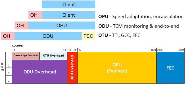
OTN (Optical Transport Network) – next-generation network, the successor of SDH.SONET. The OTN is a set of ITU-T recommendations, among which the most important one is the G.709 (‘Interfaces for the Optical Transport Network (OTN)’). It defines the OTN digital wrapper with FEC correction coding (the standard GFEC RS (255, 239) and the allowed unstandardized EFEC). OTN is nearly synonymous with DWDM since from the very beginning of designing it, a very strong support for DWDM multiplexing was built in. Like SDH networks, the OTN transmission is TDM, which results in a high signal quality, but because this is an asynchronous network (synchronization can be achieved by SDH client signals, OTN guarantees maintaining the quality of the SDH clock at the network egress), OTN equipment is simpler and cheaper than SDH equipment. The OTN wrapper consists of three basic parts: the overhead, payload, and FEC field. The size of the wrapper is 4x4080 bytes and does not depend on the transmission speed. Very strong FEC codes used allow reaching a very high optical signal robustness against signal impairments present in optical links, which enabled building transparent optical networks and networks with optical switching. Today, OTN transparently supports most relevant client protocols, including Ethernet, SDH, and FibreChannel. The hierarchy of OTN multiplexing contains client signals from 1.25G (ODU0 and ODUflex) up to 100G (ODU4). Other recommendations important for OTN development are e.g. G.872 (‘Architecture for the Optical Transport Network (OTN)’), G.959.1 (‘Optical transport network physical layer interfaces’), and G.798 (‘Characteristics of optical transport network hierarchy equipment functional blocks’).
OTN Quasi-transponder – an optical module, e.g. of XFP, Xenpak, or SFP+ type, compliant with an adequate MSA specification. Besides the standard electronics and DWDM optics, it also contains anthe OTN framing chip and FEC coder. After plugging the quasi-transponder into an optical port in any network device (e.g. IP router, Ethernet switch), the device becomes an OTN device. OTN quasi-transponders enable a low-cost DWDM OTN network construction without transponders (IPoDWDM). OTN quasi-transponders are produced by Menara Networks company.
![]()
Penalty – when calculating link signal quality budget, if transmission quality degrading mechanisms other than the dominating one are significant, the effects of second-order mechanisms are taken into account as effective quality loss caused by the dominating effect. For example in a 90 km 10G link the effect of chromatic dispersion can be accounted for as a penalty added to the power budget (1-2dB), in optically regenerated and chromatically compensated link the effect of SPM can be taken into account by adding an adequate penalty.
PDL (Polarization Dependent Loss) – each optical device has slightly different measured attenuation depending on the state of polarization of the incident light. After sweeping through all possible polarization states, the difference between the highest and lowest measured loss gives the PDL. The information about the PDL is important because in an optical network the polarization state is not controlled and typically undergoes random changes. This means that the temporary loss of each link component will be changing in a different way, depending on the component’s PDL. The PDL can be reliably measured only by sweeping through many polarization states (which is a time-consuming process), or by using the Müller matrix method.
PIN – one of the two basic types of semiconductor photodiodes used in optical telecommunication receivers. It is a semiconductor PN junction biased in the reverse direction. Unlike in the usual PN diode, a relatively thick and almost undoped layer (‘I’ stands for Intrinsic) is located between the highly doped P and N layers. In the I region, photons are caught and create an electron/hole pair, which then moves in the direction of the electrodes. This is equivalent to current flow. Comparing to the APDs, the PIN photodiode doesn’t have the avalanche gain, so it usually has a lower sensitivity, but is less noisy.
PLC (Planar Lightwave Circuits) – a common name for technologies for manufacturing integrated optical components which originate in microelectronic technologies (e.g. proton exchange, diffusion, ion implementation) that enable creation of precisely defined regions differing in refractive index (waveguides). Because PLC components are usually later connected to standard glass fiber, the whole production of PLC devices is a hybrid process. In the PLC technology, mostly PLC splitters, AWGs, and also optical switches and modulators are produced. The main advantage of the PLC technology is its scalability and small dimensions of produced components. The disadvantages are a small flexibility of the process (production of short series is extremely expensive) and usually large excess losses comparing to monolithic technologies, such as FBT (caused by mode conversion from Gaussian mode in the optical fiber to the one supported by an approximately rectangular waveguide, by high loss of substrates, and most importantly by accuracy of optical fiber alignment relatively to the waveguides). Examples of devices produced in the PLC technology are Fibrain PLC splitters and Fibrain AWG.
PLC Splitter – a type of optical power slitter produced in the PLC technology. It is a passive optical device used in fiber optic telecommunications for splitting optical power among N output ports. It usually has one output port (sometimes two). A PLC splitter, like all other passive splitters, exhibits insertion loss due to power splitting and excess losses. PLC is a hybrid technology (unlike the monolithic FBT technology), a typical PLC splitter consists of a PLC chip (in which waveguides and a tree of basic 1x2 or 1x3 splitters are manufactured by microelectronic methods) and a matrix of optical fibers in V-groves (so-called fiber array), which are glued together and packed in further protective housings. The splitter insertion loss depends on the fiber array positioning relatively to the waveguides on the chip – positioning with precision to the tenth part of micrometer is required. Moreover, the components are not allowed to shift relatively to each other during 25 years of operation, regardless of mechanical stresses, temperature, and humidity. All these requirements make good quality PLC splitter manufacturing non-trivial.
PM (Polarization Maintaining) – typical components used in optical telecommunications (including optical fiber) do not maintain polarization, i.e. the polarization of the output signal can be randomly different than the polarization of the input signal. This is caused by power coupling between the two fundamental polarization modes. In PM devices, the propagation constants of both polarization modes are so different that power coupling between them is very significantly reduced. In PM fibers, this is achieved by introducing additional stresses in the fiber, e.g in the form of rods along the core (Panda and bow-tie type fibers). To assure maintaining of constant polarization state, accurate aligning fast and slow axes of components in a PM setup is necessary. Examples of polarization maintaining components are PM connectors produced by Fibrain, as well as PM couplers and circulators.
PMD (Polarization Mode Dispersion) – in a single-mode fiber, there are actually two modes that differ in polarization (orthogonal). Each of these modes has somewhat different propagation velocity, so in a long link they appear at the output at different times, which causes impulse spreading and reduces signal. Like modal dispersion, the PMD is random and as such is hard to compensate for.
PON (Passive Optical Network) – one of the two basic architectures of FTTH optical access networks. It assumes sharing a given network segment (a port on a central OLT device) by all subscribers. This segment consists of the main section from the central active device to the passive splitting device. Dedicated fibers are then routed to each subscriber individually (from the aforementioned passive splitting device to the ONT customer terminal). The passive splitting device can be a PLC splitter (the most common solution) or a DWDM multiplexer (in DWDM PON, not widely used yet). In the case of using a PLC splitter, a multiple-access with time division (TDM, each subscriber transmits only in a time slot dedicated to them by the OLT) is used to prevent collisions among subscribers transmitting on the same wavelength in the same fiber. In the case of DWDM PON, despite a point-to-multipoint physical topology, the logical topology is star (many point-to-point connections), because each ONT transmits at a different wavelength. Transmission protocols used in PON are mostly the GPON, the GEPON, and in the future also the XG-PON (10G-PON) and the 10G-EPON. One of the most popular GPON equipment manufacturer is Dasan Networks.
PON meter – a type of optical power meter that allows power measurement at 1310/1490/1550 nm in a live PON network. Compared to the standard optical power meters it is always calibrated for the aforementioned wavelengths, has built-in optical filters, which allow for simultaneous measurement at all three wavelengths used in GPON and CATV PON, operates in the transparent mode (the PON meter is inline connected into the network without stopping the transmission, it has two optical ports, input and output), and also in the continuous wave mode (CW) as well as supports the burst mode (required due to the fact that the ONTs transmit in short timeslots allocated to them by an OLT). An example of a PON meter is the Fibrain FPPM-345.
Post-FEC BER – bit error rate at the FEC decoder output, i.e. after correction of transmission errors by the FEC decoder. In OTN networks, due to decoder characteristics steepness, there are generally either no post-FEC errors (if the number of errors in the incoming signal does not exceed correction possibilities of the used coding) or whole frames are rejected (if the number of pre-FEC errors exceeds the correction possibilities of the used coding).
Power budget – the difference between transmitter power and detector sensitivity. It is a basic measure of signal quality in links limited by thermal noise. Most CWDM links are designed for power budget. On the other hand, long DWDM links are usually limited by the amount of optical noise (OSNR) and they cannot be designed for power budget (incoming power). Using optical amplifiers enables the increase of the available power budget at the cost of generating optical ASE noise.
Pre-amp (preamp, pre-amplifier) – in optical telecommunications, an optical amplifier usually having low output power, used e.g. in front of a booster (in a two-stage amplifying node) or a detector. A pre-amp usually has a low allowed input power, high possible gain, and low noise figure (NF).
Pre-FEC BER – bit error rate at the line output, in front of the FEC decoder. The pre-FEC level depends on the quality and complexity of a link. In OTNs, it is a crucial parameter that tells if transmission can be achieved. A change in pre-FEC BER typically suggests ongoing link degradation. Any FEC forward error correction codes have limited capabilities, i.e. are able to correct a certain maximal number of corrupted bits in a frame. If the incoming signal quality is too low (pre-FEC BER level is too high), the decoder is no longer able to correct the errors and the whole frame is rejected.
QSFP/QSFP+ (Quad Small Form-Factor Pluggable) - similar in size to CXP, hot pluggable optical module used for high speed data transfer between applications. Since May 2013, the highest achievable transmission rate is 4x28 Gbit/s (such transceivers are known as QSFP28). The QSFP specification accommodates Ethernet, Fibre Channel, InfiniBand and SONET/SDH standards with different data rate options. QSFP+ transceivers are designed to carry Serial Attached SCSI, 40G Ethernet (100G using QSFP28), QDR (40G) and FDR (56G) Infiniband, and other communications standards. QSFP modules increase the port-density by 3x-4x compared to SFP+ modules.
PtP WDM PON (Point to Point Wavelength Division Multiplexing Passive Optical Network) – one of NG PON protocols. According to this protocol, data is transmitted in one channel dedicated to a given ONU (and not shared with other subscribers). The transmission can be implemented in one of the two following bands: 1603-1625 nm (Shared Spectrum option) or 1524-1625 nm (Expanded Spectrum option). The bands used should be chosen depending on the type of protocol to be implemented: it can be either only the NG-PON2 standard or also other (e.g. XG-PON).
Raman amplifier – a type of optical amplifier used in optical telecommunications which uses the stimulated Raman effect in optical fiber. A Raman amplifier is just a laser pumping high power of a proper wavelength into a length of fiber (in practice this is most commonly a transmission fiber). The stimulated Raman effect is a nonlinear phenomenon that is based on photon scattering from the optical pump on optical phonons in the presence of signal photons. As a result of stimulated Raman scattering, one pump photon (of higher energy or shorter wavelength) is transformed into a signal photon (of lower energy) and an optical phonon. To achieve an optical gain around 1550 nm, the pumping laser should operate at around 1450 nm (the Raman gain peak in optical fiber is shifted by around 12 THz relatively to the pump wavelength). To flatten the gain profile, two or three pumping wavelengths can be used. Powers of pumping lasers are of the order of a few hundred mW up to 1 W, which means that they are 3B class light sources and as such they should be fitted with mechanisms ensuring optical safety.
Rayleigh Scattering – one of the fundamental mechanisms of optical losses in glass optical fibers. It results from the amorphous structure of glass, which consists of very small grains of material of slightly differing density and refractive index. The grain dimensions are much smaller than wavelength. On the boundaries of grains, numerous small reflections occur. Because the boundaries of grains are irregular, the power can be reflected in any direction. Most of the reflected power leaves the fiber through the cladding, but the part of back-reflected power which fits into the acceptance cone set by the numerical aperture of the fiber propagates in the fiber and returns to the transmitter. The optical reflectometer operates by using Rayleigh scattering.
Receiver sensitivity – the minimum optical power that has to be delivered to the receiver for it to detect the signal correctly (usually it means BER of 1e-12 or 1e-15). For links limited by thermal noise, the knowledge about the receiver sensitivity (required to calculate the power budget) is enough to design the link. In the presence of other phenomena that decrease the signal quality, their impact may be taken into account by adding a penalty. When some other phenomenon is the main cause of signal degradation, designing the link for power budget makes no sense.
RFoG (RF over glass) – see DPON.
Return Loss (RL) – a measure of what part of optical power is lost as a result of reflecting from an optical component.
ROADM (Reconfigurable Optical Add/Drop) – a type of optical network node that allows local separation (termination) of selected channels in an optical multiplex and local addition of new optical channels. ROADM nodes are currently used only in DWDM networks. It is a network node of at least second order (connected to at least two lines). The name ‘reconfigurable’ means that wavelengths (DWDM channels) switched among the output lines in a ROADM node do not have to be pre-defined and can be remotely configured by the operator. In a traditional ROADM structure, a change of local channel configuration (i.e. terminated and starting in a given node on local transponders) requires a physical operator intervention. Only adding the colorless functionality enables a remote change of local channel wavelength, and the directionless functionality allows forwarding of a local channel to any output line. The central component of a ROADM node is usually the WSS (Wavelength Selective Switch), which functions as an optical switching matrix. The WSS can be produced in the MEMS technology, liquid crystal, or DLP and LCoS technologies. Besides optical switching, an important task of the ROADM nodes is equalizing the optical power levels of DWDM channels in an optical multiplex. Introducing the ROADM technology enabled the construction of optical networks in a lattice topology and creating the ASON/GMPLS control plane and optical restoration.
SBS (Stimulated Brillouin Scattering) – a nonlinear effect in optical fibers that appears after reaching a threshold power level. It can be recognized by a sudden increase of attenuation, while the lost optical power is backreflected (scattered) in the direction of the receiver instead of reaching the detector. In the SBS regime, raising the input power does not increase the power supplied to the detector. Moreover, it decreases the transmission quality because the power scattered as an effect of SBS can be once more backreflected (e.g. as a result of Rayleigh scattering) or reflected as a result of Fresnel reflections and it can reach the detector as noise. The SBS excitation level depends on the spectral power density, so a transmitter with a wider spectrum is more resistant to SBS than a laser with a narrow line. Due to this fact, the so-called dithering, or laser line widening, is commonly used in lasers. In CATV transmission, in which usually very high optical powers per optical channel are used when applying optical amplifiers, the SBS can be a serious obstacle in reaching a required signal quality, especially when CATV 1550 nm transmitters with a low SBS threshold are used together with high power optical amplifiers.
Second transmission window – the 1260-1360 nm wavelength range (so-called grey 1310). The name derives from the fact that these wavelengths started to be used by second generation fiber-optic transmission systems. In the ITU-T nomenclature, this is the O-band (coming from the word Original).
SFP (Small Form Pluggable) – a compact transceiver used to transmit data, voice, or image with a rate up to 5Gbit/s. Must be compliant with the appropriate MSA (Multi-Source Agreement) specification. SFP modules are used for example in SONET/SDH, Ethernet, or Fibre Channel networks. Due to their small size and small thermal load, they can be used in high-density configurations. SFP modules can be optionally supplied with the DDM (Digital Diagnostic Monitor) functionality. It allows monitoring the key parameters of module operation, such as optical power of the transmitted signal, optical power of the received signal, temperature of operation, power supply voltage, laser current. The SFP module is colloquially called the miniGBIC. SFPs are fully hot-pluggable.
SFP+ - a transceiver with the same physical dimensions as the SFP module, which enables up to 11.3 Gbit/s transmission.
SMF (Single Mode Fiber) – a frequently used name for the G.652 standard (also SSMF).
SPM (Self Phase Modulation) – One of the nonlinear phenomena resulting from the Kerr effect which occur in optical fibers. As a result of the SPM process, new frequency components are generated in the signal. This happens when the power level changes in time, which due to the Kerr effect changes the temporary value of the refractive index seen be the same signal (the signal changes transmission conditions for itself). A change of refractive index causes a change of the signal phase and leads to generation of new frequency components. This results in widening of the signal spectrum, even to the extent when the signal no longer fits in the filter passband. The widened signal is also more susceptible to chromatic dispersion (although the interplay of SPM and CD can be used to advantage in soliton transmission). In the case of phase modulated signals, phase fluctuations directly lower the transmission quality. The effectiveness of the SPM process depends on link length, optical power, and amount of chromatic dispersion. An example of spectrum evolution for 10G RZ and NRZ after propagation in a long DWDM link is shown below.
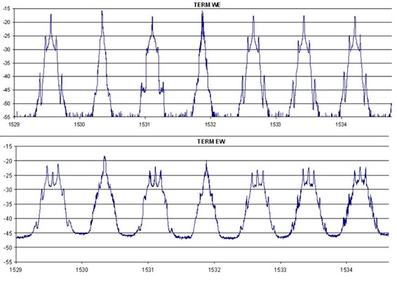
SSMF (Standard Single Mode Fiber) – a frequently used name for the G.652 standard (also SMF).
Symmetrical splitter – an optical power splitter which has N output ports, each of them carrying the same percentage of the output power, or having nominally identical attenuation. It should be noticed that in practice due to technological reasons the attenuation of output ports in symmetrical splitters is slightly different for each port (it is a so-called attenuation uniformity). Symmetrical splitters are most frequently used to connect subscribers located at a similar distance from the splitter. Typically, PLC splitters are symmetrical splitters (the Fibrain PLC 1x5 is an exception). In contrast, FBT couplers can be produced as asymmetrical with any split ratio.
TFF (Thin Film Filters) – one of the basic technologies for making optical filters (also for manufacturing filters used in telecommunications), based on depositing (usually on a glass substrate) alternating layers of high and low refractive index so that this way stacks of resonance cavities are produced . The filter central wavelength depends on the length of the resonance cavity. Wavelengths in resonance with the cavity are transmitted, and the remaining wavelengths are reflected. The larger the number of cavities the more the spectrum shape resembles an ideal rectangle at the costs of increasing attenuation (and chromatic dispersion). TFFs are the basic type of filters applied in CWDM transmission, and one of the two basic ones in DWDM transmission (with the AWGs).
Thermal noise – one of the basic electronic noises, known also as Johnson or Nyquist noise. It is caused by a chaotic movement of electrons independent of voltage. The value of thermal noise power is proportional to the temperature, which means that decreasing temperature of detector operation improves its noise parameters. Optical links designed for power budget are in reality limited by the thermal noise.
Third transmission window – 1530-1565 nm wavelength range. The name comes from the fact that these wavelengths started to be used in the third-generation fiber-optic telecommunication systems. In the third transmission window, the DWDM transmission has become popular, which results mostly from the availability of EDFA type optical amplifiers, having gain in this range, and from the fact that optical fibers have minimal attenuation in this region. In the ITU-T nomenclature, this is the C-band (‘C’ stands for Conventional).
Transponder – in optical networks, transponders are ingress and egress demarcation points (points where the traffic is input and output from the network). They are devices (usually in the form of cards inserted in a chassis) having at least two optical ports – client and line (a muxponder is a form of transponder having more client ports). Transponders at both ends of the link form points of contact between the transport network and other networks and are demarcation points at which monitoring and traffic management (and possibly SLA warranty) begins. The basic functions of transponders (especially in OTN DWDM networks) are:
-conversion of client (grey) optics to DWDM quality optics
- encapsulation and transmission protocol conversion
- implementation of the OTN functionality, increasing the available transmission distance and quality thanks to FEC coding
- providing the demarcation points, between which the optical path from the NMS level can be seen
- offering OAM functionality (operations, administration, and maintenance)
- reducing electric jitter and regenerating the signal
- ease of troubleshooting and network optimization by PRBS generators and loopback functionality
The crucial disadvantage of transponders in the cost, which in some cases can reach even 80% of OTN DWDM network costs (depending on the network functionalities). An alternative are IPoDWDM approaches, such as OTN quasi-transponders produced by Menara Networks.
 Transverse fiber modes – in the geometrical approach, transverse fiber modes are the allowed rays (optical paths) transmitted along the optical fiber. Each mode is a different configuration of the electromagnetic field with different field intensity. Single-mode fiber supports only one (fundamental) mode (in practice two modes, if polarization is taken into account), and multi-mode fiber typically a few hundreds. The fundamental mode has a field intensity profile similar to the Gaussian function, and higher-order modes have more and more complicated profiles. Fiber modes do not differ in wavelength (for one wavelength, many modes propagate in a multi-mode fiber).
Triplexer – a commonly used name of certain types of passive optical filters, especially the ones used in FTTH networks, e.g. CATV/GPON triplexers (separating the CATV 1550 nm and the GPON 1310/1490 nm signals) or in FTTH/OTDR networks (separating the OTDR 1625 and 1650 nm signals used for monitoring live networks and the traffic signals). Triplexers enable WDM transmission.
TWDM PON (Time and Wavelength Division Multiplexing Passive Optical Network) - one of the approaches to realize NG PON2-level access networks, a network standard offering up to 10 Gbit/s symmetric upstream/downstream speeds to each subscriber. The standard utilizes 1524 nm to 1544 nm wavelengths in the upstream direction and 1596 nm to 1602 nm in the downstream direction. The choice of such wavelengths ensures compatibility with older PON standards and allows OTDR measurements. WDM transmission is used downstream thanks to fixed wavelength lasers at OLT and active filters in the ONUs. Transmission in the upstream direction is accomplished by tunable lasers in the ONUs.
Unit attenuation – attenuation of optical fibers or optical fiber cables, given in dB/km. Information about unit attenuation allows calculating the total link attenuation, which is the basic step in link design. Optical fiber attenuation depends on the type of fiber and wavelength.
UPC (Ultra Physical Contact) – a standard of fiber optic connectors with the endface polished perpendicularly to the fiber axis. Comparing to earlier perpendicular polishing standards (PC – Physical Contact and SPC – Super Physical Contact), a much better value of return loss of a closed connector, of the order of 55 dB, was reached (the return loss of a UPC connector open to the air is about 14.6 dB. It is caused by Fresnel reflections). Today, UPC polishing is so common comparing to the PC and SPC that manufacturers often use the PC designation for describing the UPC polishing.
Water Peak – in glass optical fibers, a water peak traditionally appeared due to OH ion absorption around 1383 nm. That is, there was a spectral region of raised and uncontrolled optical fiber attenuation. The presence of the water peak in practice prevented using CWDM channels around 1383 nm (mostly 1371 nm and 1391 nm) because creating a reliable theoretical link design for these wavelengths was impossible and referring to the measured values was always necessary with the additional notice that the attenuation around the water peak can increase in time as more water is absorbed by the fiber. Only the C and D versions of the G.652 recommendation defined a single-mode fiber without a water peak, having the whole band between 1270 nm and 1610 nm available for use. The fibers of G.652 C and D standards are known as “low water peak fiber, LWPF” or “zero water peak fiber, ZWPF”. Special technological process (deuterization) is required during production that prevents the fiber from water absorption and recreating the water peak after installation. Cases of less-renowned suppliers are known, when fibers initially without a water peak restored it with time. It is worth to notice that even if the peak is located in relatively rarely used 1383 nm band, the slopes stretch to at least 1320 nm on one side and 1470 nm to the other side of the peak, so the presence of water peak can affect the attenuation of wavelengths situated far from 1383 nm.

WDM (Wavelength Division Multiplexing) – a method of multiplexing in the wavelength domain used in fiber-optic transmission. Strictly speaking, the WDM is a general name for all kinds of wavelength multiplexing, and in practice it functions as a synonym for WWDM. Wavelength multiplexing is a method of optical transmission that allows sending more than one channel in one optical fiber (even up to almost 200 channels in the DWDM method). Besides the WWDM and DWDM forms, the CWDM variant is also popular.
WWDM (Wide Wavelength Division Multiplexing) – a method of multiplexing in the wavelength domain used in fiber optic transmission. According to the definition in the G.671 recommendation (‘Transmission characteristics of optical components and subsystems’), it is a transmission method in which the channel separation is at least 50 nm. The central wavelengths for WWDM transmission were not standardized in the G.671, but 1310 nm and 1550 nm are commonly used. Using two wavelengths means doubling the link’s capacity. The WDM method is most frequently used in performing a bidirectional transmission in one optical fiber. In such a case, optical modules (transceivers) have built-in adequate 1310/1550 nm passive multiplexers. Lasers dedicated for WWDM transmission have very wide deviations of the central wavelengths, of the order of +/- 50 nm. In CATV and GPON networks, other wavelengths (1490 and 1550 nm) separated from other channels by more than 50 nm are used, but the lasers are not of the WWDM quality (in practice, the lasers are of the CWDM class).
Xenpak – a transceiver format used in optical telecommunications with the 10Gbit Ethernet standard. It supports transmission on single-mode and multi-mode fibers, can be extracted during operation (is hot pluggable), and has SC type connectors. Replaced by the smaller XFP (Xenpak has dimensions 121 x 36 x 18 mm, and XFP 71 x 18.5 x 8.5 mm).
XFP (10 Gigabit Small Form Factor Pluggable) – another transceiver format used in optical telecommunications with a rate of at most 11.3Gbit/s. It can be extracted during operation (is hot pluggable) and has LC type optical connectors.
XG-PON – also known as the 10G-PON, the successor of the GPON standard. It is a standard of the next-generation PON (NG-PON) created by the ITU-T. It was designed for FTTH networks and for ensuring even faster access in the last mile. The standard is divided into two rate categories: XG-PON1 (an asymmetrical version offering 10Gbit downstream and 2.5G upstream) and XG-PON2 (symmetrical version offering 10G downstream and upstream). The XG-PON standard is able to operate in the same PON as the GPON, which requires only an additional WDM splitter. This is due to the fact that the XG-PON uses different wavelengths, i.e. 1575-1580 nm downstream and 1260-1280 nm upstream. Much more information about the XG-PON networks can be found in our white paper here.
XGS PON - 10G symmetrical passive optical network standardized by the ITU-T in G.9807.1 (06/16) recommendation; see XG-PON.
XPM (Cross Phase Modulation) – One of the nonlinear phenomena resulting from the Kerr effect (refractive index dependence on optical power), which occur in optical fibers. Similar to the SPM, but the power which modifies the refractive index value is the total power of all neighboring channels that affect the inspected channel in this way. When many neighboring channels propagate, the result of the summed XMP is a phase noise, which is then converted into amplitude noise and jitter by chromatic dispersion. The strength of the XPM depends on the amount of chromatic dispersion and optical power levels.
YEDFA (Ytterbium-Erbium Doped Fiber Amplifier) – a kind of optical EDFA in which ytterbium ion doping of the active medium is used along with the erbium ion doping. Optical amplifiers with very high power are produced in this way (mostly multiport power boosters for CATV FTTH transmission, e.g. 32x21dBm Fx-OV32210 produced by BKtel Communications).
ZWPF (Zero Water Peak FIber) – optical fiber with a reduced water peak.